Knowing a filler metal with an A5.36 open classification provides improved toughness potentially reduces the need to carry out additional qualification testing based on new materials and welding requirements. A5.36 welding wires and electrodes will still retain their fixed classifications to help avoid issues with existing welding procedures.
GMAW (MIG welding) electrodes are designated by some letters and numbers such as ER70S-6, ER90S-6 and E308L etc. I will explain the meaning of these symbols:
- Welding Filler Metal Classifications, ASME IX F-numbers A-numbers.
- In filler metal specification AWS A5.1, low hydrogen carbon steel SMAW electrodes are identified with the last 'X' number in the designator EXXXX as a 5, 6 or 8. A5.1 SMAW low hydrogen electrode classifications include E7015, E7016, E7018, E7018M, E7028.
- CLASSIFICATIONS OF STEELS Base Metals Code Designations and Filler Metal Classifications as per AISI, SAE, ASME and CSA AISI American Iron and Steel Institute SAE Society of Automotive Engineers ASME American Society of Mechanical Engineers CSA Canadian Standards Association AISI-SAE Classification of Steels Classifications Specifications.
FOR CARBON STEEL OR MILD STEEL (SUCH AS ER70S-6 OR ER70S-3)
Where,
ER – Designates electrode or filler rod
XX – Designates the minimum tensile strength of the deposited weld metal

S – Stands for solid wire
Y – Designates the chemical composition of the additives such as deoxidizing agent or cleansing agent used on the electrode, it may affect the polarity setting also.
FOR EXAMPLE:
Aws Filler Metal Specification
ER70S-6
Where,

ER – Designates a welding electrode or filler wire
70 – Designates the minimum tensile strength of the deposited weld metal shall be 70 Ksi or 70,000 Psi
S – Stands for solid wire
6 – Reflects the amount of oxidizing agent and cleansing agent on the electrode. In particular the number 6 means that more deoxidizers have been added to the wire, which is helpful when welding on dirty or rusty steel.
FOR STAINLESS STEEL
Stainless steel electrodes are designated in a slight different way. Some of the commonly used stainless steel electrodes are ER308L and ER309L etc. Meaning of these symbols is explained below;
ER308L
Where;
ER – Stands for electrode or filler wire
308 – Designates the grade of stainless steel of the electrode or filler wire

L – Designates that it is a low carbon electrode
FOR ALUMINIUM
For Aluminum, electrodes are designated as ER4043, ER5350 etc. These electrodes are designated in a different way. For example;
ER4043

Where,
ER – Stands for electrode or filler wire
4 – Designates series of Aluminum of which the electrode is made from. In this case it’s a 4000 series Aluminum
043 – Reflects the amount of silicone added to the electrode
SHIELDING GAS:
GMAW requires a shielding gas, to protect the weld pool from atmospheric contamination. Following gases are used as shielding gas;
- Argon
- Carbon Dioxide
- Helium
(NOTE: Whenever Carbon dioxide is used as shielding gas in Gas Metal Arc Welding (GMAW). The term MAG (Metal Actve Gas) welding is used, because Carbon dioxide is an active gas. Whereas, other shielding gases such as Argon and Helium are inert in nature. Hence, whenever theses gases are used as shielding gas, the term MIG (Metal Inert Gas) welding is used.)
These gases are used alone or a combination of gases can also be used. Commonly used combinations of inert gases are;
- 75% Argon + 25% Carbon Dioxide (most popular combination)
- 98% Argon + 2% Carbon Dioxide
Argon helps in achieving cleaner weld whereas, Carbon dioxide helps in getting a deeper penetration. Carbon dioxide can be used alone also and it is effective while welding thinner metals.
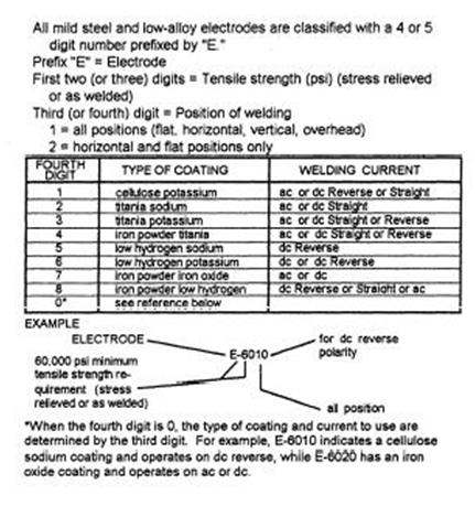
Filler Metal Specification And Classification Chart
Relationship between filler wire diameter, current range and wire feed speed:
In MIG/MAG welding, Voltage, Current and wire feed speed must be controlled for sound welding
The Voltage controls the weld profile. Whereas, the Current controls the heat input, size of weld and the depth of penetration.
The following table (Table – 1) gives the current range and the filler wire feed speed, based on the filler wire diameter. This table is just a guide and the ranges may vary depending upon the shielding gas and parent metal.

Table – 1
| S.No. | Diameter (mm) | Current Range (A) | Wire feed speed (m/min) |
| 1 | 0.6 | 40 – 100 | 2 – 5 |
| 2 | 0.8 | 40 – 150 | 3 – 6 |
| 3 | 1.0 | 100 – 280 | 3 – 12 |
| 4 | 1.2 | 120 – 350 | 4 – 18 |
